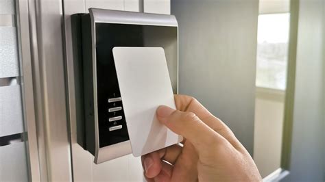
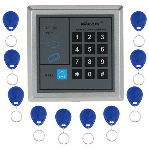
rfid access control system wiring diagram The wiring diagram for an RFID Access Control System is designed to provide a visual representation of the system’s components and how they interact. The diagram will .
Step 4: Using NFC Cards on the Nintendo Switch. With the NFC cards registered, you can now use them on the Nintendo Switch. To activate the desired functionality, simply place the NFC card near the NFC scanning area .
0 · rfid key card entry systems
1 · rfid door entry system
2 · rfid disadvantages for gate control
3 · rfid based door access control
4 · rfid access control system price
5 · rfid access control system pdf
6 · rfid access control system manual
7 · access control using rfid system
$19.99
The materials required for this access control system include: 1. Magnetic lock with a mounting bracket (fail-safe type lock) 2. DC power supply adaptor or switched-mode power supply (SMPS) (12V, 3A) 3. Access control reader 4. Exit push button 5. Connecting wires (Cat 6 or copper wires, as required) See moreThe block diagram of the access control system is shown in Fig. 1. It is built around a magnetic lock with mounting brackets, a 12V SMPS/adaptor for the power supply, an access control device, an exit push button, RFID tags, cables. It includes 3- and 6-pin connectors . See moreWhen a pre-registered user or authorized person tries to open the door using an RFID tag (card) or password or biometrics, the relay circuit gets activated and the COM terminal gets . See more This access control system can use a standard RFID reader that uses card credentials, or a smartphone door reader, a biometric door reader, or even one that .
Standalone RFID Door Access control System | Connection Diagram | Practical Connection | Working. Door Access Control System & Security Solutions, What is Door .
The wiring diagram for an RFID Access Control System is designed to provide a visual representation of the system’s components and how they interact. The diagram will .This Installation Guide explains how to install and configure FREUND IP-INTEGRA Access Control Units and FREUND ACC-Readers. Please read this User Manual carefully before .Access Control System Function (1) When a registered user's identity is verified, the Access Control device will send out signal to unlock the door. (2) The door sensor will detect the .
The Rfid Access Control Ad2000 M Wiring Diagram is designed to meet the security needs of a wide range of applications. It includes components such as readers, door .
Features: Ability to verify and control access with RFID card and password. Resistance to water ingress allows the device to be installed as an external access system to .The standard HID card reader wiring diagram consists of several key components, including the reader itself, an access control panel, a power supply, and an electric lock or door strike. . With its advanced integration of radio frequency identification (RFID) technology, the YH2000 C wiring diagram offers a wide range of features that make access control faster, . RFID and Password-Based Access Control System: Wiring Installation Diagram. The block diagram of the access control system is shown in Fig. 1. It is built around a magnetic lock with mounting brackets, a 12V SMPS/adaptor for the power supply, an access control device, an exit push button, RFID tags, cables.
This access control system can use a standard RFID reader that uses card credentials, or a smartphone door reader, a biometric door reader, or even one that recognizes faces and measures a person’s temperature. Standalone RFID Door Access control System | Connection Diagram | Practical Connection | Working. Door Access Control System & Security Solutions, What is Door Access Control.Access Control System Function (1) When a registered user's identity is verified, the Access Control device will send out signal to unlock the door. (2) The door sensor will detect the status of the lock. If the door is unexpectedly opened or improperly closed, the alarm will be triggered. The Rfid Access Control Ad2000 M Wiring Diagram is designed to meet the security needs of a wide range of applications. It includes components such as readers, door controllers, and power supplies, allowing for easy integration into existing security systems.
The standard HID card reader wiring diagram consists of several key components, including the reader itself, an access control panel, a power supply, and an electric lock or door strike. These components are interconnected with various wires and cables to ensure proper functionality.
rfid key card entry systems
rfid door entry system


This Installation Guide explains how to install and configure FREUND IP-INTEGRA Access Control Units and FREUND ACC-Readers. Please read this User Manual carefully before using the product.
With its advanced integration of radio frequency identification (RFID) technology, the YH2000 C wiring diagram offers a wide range of features that make access control faster, easier and more reliable.
What does the wiring diagram for access control system look like? Find out the different types of cables and wires that your security system needs.
Learn how to make Arduino RFID/NFC Door Lock system, how to use RFID/NFC tag to unlock the door, how to make a security door lock system, how to program Arduino step by step. The detailed instruction, code, wiring diagram, video tutorial, line-by-line code explanation are provided to help you quickly get started with Arduino.
RFID and Password-Based Access Control System: Wiring Installation Diagram. The block diagram of the access control system is shown in Fig. 1. It is built around a magnetic lock with mounting brackets, a 12V SMPS/adaptor for the power supply, an access control device, an exit push button, RFID tags, cables. This access control system can use a standard RFID reader that uses card credentials, or a smartphone door reader, a biometric door reader, or even one that recognizes faces and measures a person’s temperature. Standalone RFID Door Access control System | Connection Diagram | Practical Connection | Working. Door Access Control System & Security Solutions, What is Door Access Control.Access Control System Function (1) When a registered user's identity is verified, the Access Control device will send out signal to unlock the door. (2) The door sensor will detect the status of the lock. If the door is unexpectedly opened or improperly closed, the alarm will be triggered.
The Rfid Access Control Ad2000 M Wiring Diagram is designed to meet the security needs of a wide range of applications. It includes components such as readers, door controllers, and power supplies, allowing for easy integration into existing security systems.The standard HID card reader wiring diagram consists of several key components, including the reader itself, an access control panel, a power supply, and an electric lock or door strike. These components are interconnected with various wires and cables to ensure proper functionality.
This Installation Guide explains how to install and configure FREUND IP-INTEGRA Access Control Units and FREUND ACC-Readers. Please read this User Manual carefully before using the product. With its advanced integration of radio frequency identification (RFID) technology, the YH2000 C wiring diagram offers a wide range of features that make access control faster, easier and more reliable.What does the wiring diagram for access control system look like? Find out the different types of cables and wires that your security system needs.

rfid disadvantages for gate control
rfid based door access control
Washington Redskins 20 at Philadelphia Eagles 6 on January 5th, 1991 - Full team and player .
rfid access control system wiring diagram|access control using rfid system